- info@mteturkey.com
- +90 (312) 309 20 86
- +905492856945
English


Products
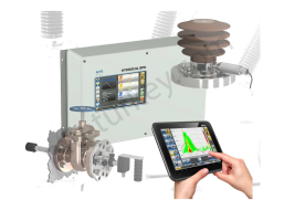
·HYDROCAL BPD is a modular online monitoring system for high voltage bushings as well as partial discharge of bushings and the active part of power transformers. Bushing monitoring supports both the measurement of voltage and phase angle on the test tap to derive tanδ/PF and bushing capacitance as well as electrical partial discharge measurement acc. IEC 60270. For the partial discharge analysis within the active part of high voltage power transformers UHF (ultra-high frequency) measurement is supported.
·HYDROCAL BPD can be combined with other HYDROCAL models, preferably HYDROCAL genX, in order to set up a comprehensive monitoring system.
As per CIGRÉ Working Group A2.37 bushings resp. the lead exit represent the 2nd largest group of transformer failure locations (approx. 25%) after the windings (43%) and before the tap changer (23%) therefore bushing monitoring can help to reduce those failures whereas UHF partial discharge analysis of the active part of a power transformer is an ideal combination with online DGA performed by the HYDROCAL product family.
The modular concept of HYDROCAL BPD allows the user to select the combination of bushing monitoring and partial discharge functions that suits best to its monitoring needs and technology convictions. Whereas the measurement of voltage and phase angle on the test tap of high voltage bushings allows to compare tanδ/PF with factory test results the partial discharge analysis could help to detect electrical failures of those bushings faster. UHF (ultra-high frequency) partial discharge analysis of the active part of large power transformers can be a good method to determine winding or other electrical failures without disturbances e.g. by corona.
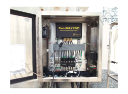
·Transformer bushing failures sometimes occur outside the capacitive layers, where traditional analysis of leakage currents will not give indication of an internal problem.
·When the utmost in transformer reliability is required for critical transformer assets, partial discharge detection must be part of the monitoring strategy. The TransMAX 2000 performs all the test methods of the ZVCM-1001 but also monitors for partial discharge (PD). The PD activity in the bushings is monitored in parallel with the power factor calculations.
·PD is detected using the same bushing sensor as with the ZVCM-1001, there are no other sensors or Rogowski coils.
·PD is caused by defective insulation in high-stress areas, movement of energized parts, or design errors where lowlevel discharges occur. Some types of PD may not present a problem, but others can develop into surface tracking or insulation failure, which can lead to bushing or transformer failure.
·The TransMAX 2000 also has the unique capability of monitoring GIC events and trends which potentially could damage the transformer.
·Easy-to-use MultiTool software works with both the TransMAX 2000 and ZVCM-1000.
Additional Specifications TransMAX 2000
·Power Supply Input Operating Range: 85-264 VAC, 120-370 VDC, 50 VA
·PD Frequency: HF <20 MHz
·PD Resolution: 1.0°
·Time Resolution: 10 nS
·Dynamic Range: 65 dB
·PD Intensity: 0 – 5000 mW
·PD Amplitude: 0.02 – 100 nC ± 10 V
·Top oil temperature sensor input
·Three load current CT sensor inputs
·Ambient Temperature and Humidity sensor inputs
·USB port for ZTZ software configuration, commissioning and data analysis
·RS-485 port for SCADA access
·Modbus RTU or DNP 3.0 Serial
·Ethernet port remote access via ZTZ Software, SCADA access over Modbus TCP or
·DNP over Ethernet Outputs
·PF, C1, leakage current for each bushing
·Imbalance for each group of 3 bushings
·PD power, PD amplitude, PD pulse count for each channel
·PRPD plots for each channel
·Top oil temperature
·Load currents
·Hot-Spot temperature
·Ambient temperature and humidity

· The phase currents can be adjusted one by one.
· Currents, phase angles(symmetric,asymmetric) and frequencies can be easily identified via the display.
· Its total weight is less than 5 kg.
· With the RS232 interface, the source has the possibility of remote access.
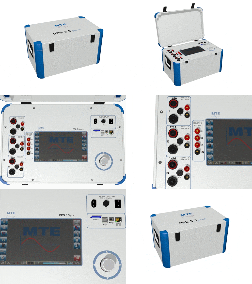
·The PPS 3.3 genX is a powerful and portable threephase current and voltage source. All test values are generated absolutely synthetically with a high degree of accuracy and stability.
Advantages of the PPS 3.3 genX
·Three-phase portable precision type source with single-phase mains supply.
·Current and voltage source facilities can be selected independently.
·Large 9” (800 x 480 pixels) TFT touch screen colour display with graphical user interface.
·Indication of load values, vector diagram and waveform.
·Current, voltage and phase shift are adjustable to high accuracy individual per phase.
·The values set are stabilised by digital and analogue control.
·Generation of harmonics (up to 31st).
·Generation of ripple control signals
·Data transfer and communication via USB (Type B), ETHERNET or WLAN
·Built in web server for remote display of graphical user interface and remote control of the unit.
·Data storage on removable SD memory card.
·Two USB (type A) connectors for connection of peripherals like mouse, keyboard.

·It is a three-phase current and voltage source with a single-phase mains supply.
·Current and voltage sources can be selected and adjusted independently of each other.
·Current, voltage and phase angles can be adjusted with high precision.
·The set values can be seen on the device screen and can also be read remotely via the RS 232 C interface.
·The set values are balanced by digital and analog control.
·31. It can be loaded harmonic up to harmonic.
·The Portable Control Module PCS 400.3 can be independently, and the power supply is controlled by bluetooth in this application.
Options
·CALegration software is used in the Windows application.

Characteristic features:
·Wide measuring December and precision.
·Portable 3 phase meter tester.
Advantages
·It is a sensitive test system for AC values and all measurement modes.
·Current and voltage December: 1 mA....120 A / 0.04 V.....480 V /45 Hz....66 Hz.
·6 current inputs allow both primary and secondary currents to be measured simultaneously in measurement systems connected to AT.
·Replaceable memory card for measurement results and customer information.
·Integrated RS 232 communication interface for data transfer to PC or program control with an external PC and written output feature.
Functions
·Active, visible power and energy measurement.
·Error measurement of 3 inputs at the same time.
·Load measurement and ratio testing of current and voltage transformers.
·Vector diagram display for analysis of basic conditions.

Advantages
·The CheckMeter 2.1 Portable Working Standard is a single-phase portable electronic meter test unit of accuracy class 0.2%, used for testing single phase electricity meters on site.
·Precision test equipment for AC values in the 45 Hz to 66 Hz frequency range.
·Wide measuring range with auto ranging.
·Easy detection of circuit connection faults.
·Data memory for test results and customer data.
·Small dimensions and light in weight.
·Serial interface (RS 232) for data transfer.
Functions
·Active, reactive and apparent energy measurement with integrated error calculator.
·Impulse output for energy (galvanic isolated).
·Current and voltage measurements.
·Phase angle measurement.
·Power factor measurement.
·Frequency measurement.

The CheckMeter 2.3 genX Portable Standard Meter is a three-phase portable electronic meter test unit of accuracy class 0.2, used for testing single and three-phase electricity meters on-site. The unit has direct voltage inputs and one UCT Universal Current Transducer input, which can be used with different independent transducers to measure the current with clamp-on CT’s or direct or with high voltage current sensors.The UCT 120.3 set of 3 active error compensated clamp-on CT’s in the range 10 mA …120 A is included in the standard accessories.The CheckMeter 2.3 genX can be upgraded to class 0.1,if the optional UCT I.3-12A input box for direct current connection is used.
Advantages
·Large 7” (800 x 480 pixels) TFT touch screen colour display with graphical user interface.
·Data transfer and communication via USB (Type B) and WLAN.
·Built in web server for remote display of graphical user inter-face and remote control of the unit.
·Data storage on removable SD memory card.
·Independent UCT sets of current transducers allow service, calibration or later purchase of clamp-on CTs or current sen-sors without factory return of the device.

It is intended for checking and calibration of reference standard power and energy meters, for calibration of precision current and voltage sources and for verification of electrical standard measurements and electricity meter test systems. The unit uses analogue – digital converters (ADCs) for its data acquisition, these being controlled and read by a digital signal processor (DSP).
The comparator may be directly connected to an external computer system over its RS 232 C serial interface. The comparator is distinguished by having very wide measuring ranges for all AC values while still being of accuracy class 0.01%:
Voltage: 30 V … 500 V
Current: 50 mA … 160 A.
In addition low currents from 1 mA are measured. Range selection may be made either manually or automatically. The advanced conception of the K 2006 Comparator
is based on our considerable previous experience of reference standard meters and comparators. The instrument is capable of measuring all principle parameters of a mains frequency network, from 15 to 70 Hz, and harmonics up to 3500 Hz. The basic accuracy of the system is 0.01%. The transfer error of the unit can be verified at any time by using an external DC reference voltage.
Features:
·Excellent price / performance ratio.
·Universal unit for many applications.
·One wide range input for each signal: Voltage:30 V – 500 V.
·Current: 1 mA – 160 A.
·High precision and long term stability.
·Can be used with computer system.
·Automatic range switching.
·Analogue – digital data acquisition with 6 x ADCs.
·Verification against D.C. reference voltage.
·Error calculator for test of reference standard meters.
·Harmonics measurement up to 32nd.
·Display of vector diagram or waveform.